Crestron AMP-2100-70 Handleiding
Hier is de Crestron AMP-2100-70 (Receiver) gebruikershandleiding. 2 pagina's in taal Engels met een gewicht van 0.9 Mb. Als u geen antwoorden op uw probleem kunt vinden Vraag het onze community.
Pagina 1/2
DO GUIDE
AMP-150-70/AMP-150-100/AMP-225/AMP-1200-70/AMP-1200-100/
AMP-2100/AMP-2100-70/AMP-2100-100
Modular Ampliers
The Crestron® Modular Amplier Series can be congured for individual module use on a at surface or
ganged together (one or more modules) with the slide-lock system for installation in a 1U rack space.
The ampliers are functionally similar to each other with varying capabilities. For simplicity within this
guide, the term “amplier” is used except where noted.
DO Assemble the Device
If a single amplier is to be used on a at surface, refer to “Placing onto a Flat Surface.” Otherwise,
continue below for instructions on creating an amplier assembly that can be placed in a standard
equipment rack. The only tools needed are a #1 or # 2 Phillips screwdriver, and a 1/4" nut driver.
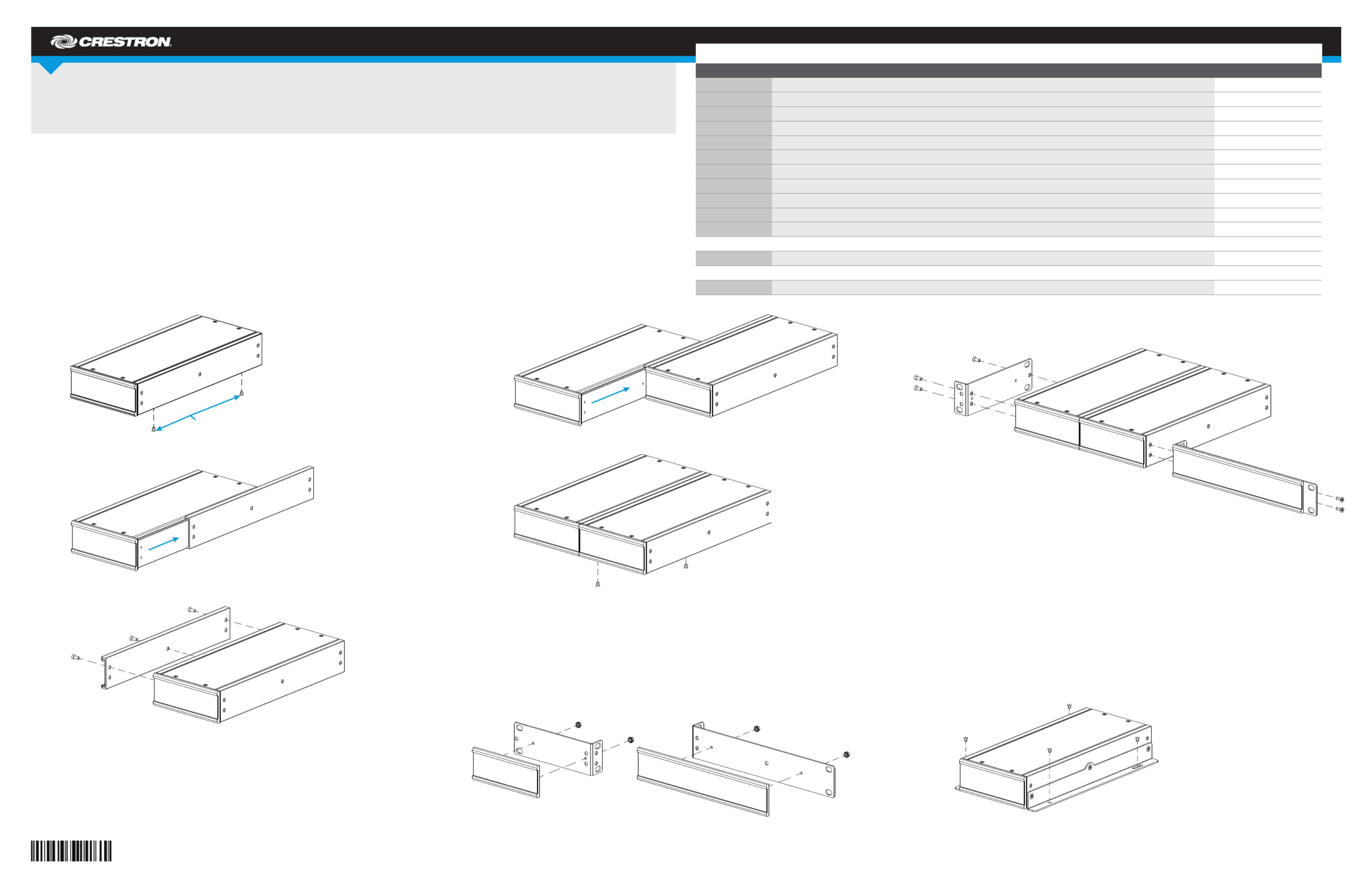
Gang Ampliers Together
Perform the following procedure to gang ampliers together. Refer to the diagrams.
1. Remove the two screws securing rail 1 to the amplier (unit 1).
2. Remove rail 1 from unit 1 by sliding it off the side of the amplier.
3. Attach rail 1 to unit 2 using the three included Phillips-head screws. Make sure that the screw
holes on the underside of rail 1 are on the bottom.
NOTE: Do not remove rail 2.
4. Slide unit 1 into the unit 2 assembly.
5. Secure unit 1 to the unit 2 assembly with the two screws removed in step 1.
6. Repeat steps 1 through 5 for additional ampliers.
Congure for Rack Installation
Before an amplier can be installed in a rack, additional hardware must be installed.
Assemble Faceplates
When an amplier or group of ampliers is not wide enough to mount in a rack, faceplates must be
assembled to “widen” the amplier to t. Assemble a faceplate by attaching an extrusion plate to a
quarter-width or half-width rack ear, as shown in the following diagrams. Secure the extrusion plate to
the rack ear using a 1/4" nut driver and the included nuts.
Attach Rack Ears to Ampliers
Attach the faceplate bracket(s) or rack ears, as required, to the amplier(s). Refer to the following
diagram for details.
NOTE: Do not attach faceplates to rack ears that are attached to the length of the amplier.
DO Install the Device
Once assembled, the amplier can be mounted into a rack, mounted onto a at surface, or placed onto
a at surface.
Mount into a Rack
Each amplier occupies 1U of rack space. Using a #1 or #2 Phillips screwdriver, mount the device into
the rack using four mounting screws (not included).
Mount onto a Flat Surface
1. Install the wall mount brackets with three Phillips-head screws (included) per side.
2. Secure the amplier to a at surface using four mounting screws (not included).
Place onto a Flat Surface
Attach the included feet to place the amplier(s) on a at surface.
DO Check the Box
QUANTITY ITEM PART NUMBER
1 Attenuator Cover, Magnetic, Security 4525789
2 Bracket, Wall Mount 2046992
1 Connector, 5-Pin 2003577
1 Extrusion Plate, Half-Width 4525245
1 Extrusion Plate, Quarter-Width 4525244
4 Foot, 0.5" x 0.5" x 0.23", Adhesive 2002389
4 Nut, 04-40, Keps 2004878
1 Power Cord, 6' 7" (2 m) 2001134
1 Rack Ear, 1U, Half-Width 2046652
1 Rack Ear, 1U, Quarter-Width 2046651
6 Screw, 6-32 x 3/8", Undercut Head, Phillips 2007235
AMP-150-70, AMP-150-100, AMP-1200-70, and AMP-1200-100 Only
1 Connector, 2-Pin 2044402
AMP-225, AMP-2100, AMP-2100-70, and AMP-2100-100 Only
2 Connector, 2-Pin 2044402
Remove these
screws.
Unit 1
Rail 1
Unit 1 Rail 1
Unit 2
Rail 2
Rail 1
Unit 1 Unit 2 assembly
Unit 1
Unit 2 assembly
Quarter-size rack ear
(no faceplate attached) Half-size faceplate bracket
Quarter-size faceplate bracket Half-size faceplate bracket
Probleemoplossing Crestron AMP-2100-70
Als je de handleiding al zorgvuldig hebt gelezen maar geen oplossing voor je probleem hebt gevonden, vraag dan andere gebruikers om hulp
Specificaties
| Merk: | Crestron |
| Categorie: | Receiver |
| Model: | AMP-2100-70 |