Crestron
Niet gecategoriseerd
CLX-2DIMU8
Crestron CLX-2DIMU8 Handleiding
Hier is de Crestron CLX-2DIMU8 (Niet gecategoriseerd) gebruikershandleiding. 2 pagina's in taal met een gewicht van 822,539.0 Mb. Als u geen antwoorden op uw probleem kunt vinden Vraag het onze community.
Pagina 1/2
The Crestron® CLX-1DIMU4-HP and CLX-2DIMU8 dimmer modules
provide universal dimming control for LED, incandescent, magnetic
low-voltage, electronic low-voltage, and 2-wire dimmable fluorescent
lighting loads.
The dimmer modules pair with CLT-1DIMU4 and CLT-2DIMU8 terminal
blocks to facilitate simple system wiring. The terminal blocks ship
separately to allow termination and testing of the field wiring prior to
the installation and setup of the CLX-1DIMU4-HP and CLX-2DIMU8.
The CLX-1DIMU4-HP ratings:
• Power feed: One - 16 A, 120 VAC
• Dimming channels: Four - 10 A (1,200 W) max per channel
• Maximum output: 16 A (1,920 W)
The CLX-2DIMU8 ratings:
• Power feed: Two - 16 A, 120 VAC
• Dimming channels: Eight - 4 A (480 W) max per channel
• Maximum output: 32 A (3,840 W)
The dimmer modules and terminal blocks are designed to install in a
CAEN enclosure (not supplied) as part of a centralized lighting control
system.
Check the Box
Item Qty
CLX-1DIMU4-HP or CLX-2DIMU8* 1
Cable, Interconnect (P/N 4500250) 1
Screw, 8-8B x 1/4 in., Pan Head, Phillips (P/N 2007277) 4
CLT-1DIMU4 or CLT-2DIMU8* 1
Label, Terminal Block, 120 V, Left 1
Label, Terminal Block, 120 V, Right 1
Screw, 8-8B x 1/4 in., Pan Head, Phillips (P/N 2007277) 2
* The dimming modules and terminal blocks ship separately.
Installation Overview
Unless otherwise indicated, the lighting system specified in this guide
is modular, requiring assembly in the field by a licensed electrician in
accordance with all national and local codes.
Contact Crestron customer support if an assembled UL® Listed panel
is required. This includes complete in-factory system configuration and
assembly by Crestron for an additional fee.
WARNING:
• The CLX-2DIMU8 can be powered from multiple circuit breakers.
• A licensed electrician must mount these devices into the CAEN
enclosure in accordance with all national and local codes.
• When connecting to a third-party arc fault breaker, ensure
the load does not exceed 1,000 watts total. Crestron certified
breakers have a 2,000-watt limit.
CAUTION: This equipment is for indoor use only and needs to be air
cooled. Mount in a well-ventilated area. The ambient temperature
must be 32° to 104°F (0° to 40°C). The relative humidity must be
0% to 90% (noncondensing).
IMPORTANT NOTES: When controlling magnetic low-voltage
transformers:
• Do not use to dim or switch magnetic transformers
greater than 100 VA for the CLX-2DIMU8 and 300 VA for
the CLX-1DIMU4-HP.
• Do not hot plug transformers or add or remove bypass jumpers
while the output channel is energized.
• Do not mix magnetic and electronic transformers on the same
output channel.
Failure to follow the guidelines above can lead to damage of the
dimmer module and transformers.
Install and Wire the Terminal Block
Install the Terminal Block
Install the terminal blocks into the lowest available space in the CAEN
enclosure. Mount additional terminal blocks into the next space above
it. Refer to the CAEN Installation Guide (Doc. 5940) at
www.crestron.com for complete mounting information.
1. Turn the power OFF at the circuit breaker(s) or fuse panel(s).
2. Remove the backing from the terminal block label. Align the holes
on the label with the holes on the enclosure and attach the label
to the enclosure.
• Use the Left Terminal Block Label when mounting into a
single-wide CAEN enclosure or into the left side of a double-
wide CAEN enclosure
• Use the Right Terminal Block Label when mounting into the
right side of a double-wide CAEN enclosure.
3. Place the terminal block over the terminal block label and secure
the terminal block to the enclosure using two supplied 8-8B x 1/4
in. screws. The colors on the terminal block match the colors on
the terminal block label.
CAUTIONS:
• Bypass jumpers are provided to test the circuits and to protect
the module during installation. When properly secured by five
screws, the jumpers on the black and red sections of the terminal
block shorts line in to dim out so that the circuit is energized. Do
not remove the bypass jumpers until all feed and load wiring has
been completed, the circuit has been tested for electrical faults,
and the module has been installed. Refer to “Module Installation
and Wiring” for details.
• Do not remove the jumpers on the white sections of the terminal
block that tie the neutral in and neutral out wires.
Wire the Terminal Block
Connect the feed (Line and Neutral) and the load (controlled circuit)
wires to the terminal block. For 2-feed systems, the two power feeds
can be different phases. Follow the labeling on the wiring label.
NOTE: Use copper conductors only, rated 75 °C or greater.
When connecting wires:
• Use 14-10 AWG wire.
• Strip wire to 1/2 in. (13 mm).
• Tighten the terminal blocks to 9 in.-lb.
Connect the Ground wires to the ground bus inside the enclosure:
• Strip wire to 1/2 in. (13 mm).
• Tighten 14-10 AWG wire to 35 in.-lb.
• Tighten 8 AWG wire to 40 in.-lb.
• Tighten 6-4 AWG wire to 45 in.-lb.
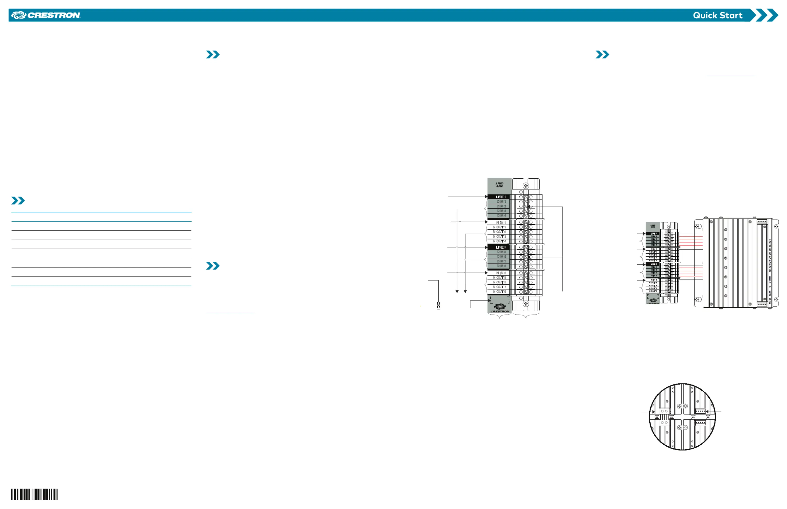
Connect the Feed and Load Wires to the Terminal Block
(CLT-2DIMU8 Terminal Block Shown)
LINE 1
Connection from a 15
or 20 A circuit
breaker
Bypass
jumpers
Terminal
block
To loads
Left-side
wiring label
LINE 2
Connection from a 15
or 20 A circuit
breaker
Ground
bus
NEUTRAL
NEUTRAL
GND
CLX-2DIMU8
DIM 1
DIM 2
DIM 3
DIM 4
DIM 5
DIM 6
DIM 7
DIM 8
N IN 1
N OUT 1
N OUT 2
N OUT 3
N OUT 4
N IN 2
N OUT 5
N OUT 6
N OUT 7
N OUT 8
LINE 1
LINE 2
2 FE ED
8 DI M
120VAC 60 Hz
SINGLE PHASE
16A MAX/FEED
Module
location
label
NOTES: When wiring the terminal block on right-side double-wide, the
connection points on the label are reversed.
Test the Terminal Block Wiring:
1. Turn the power ON at the circuit breaker(s) or fuse panel(s).
2. Verify that the circuit breakers do not trip.
3. Verify that the power is delivered to the proper loads.
4. Repeat steps 1-3 for the other circuit breaker.
Install and Wire the Dimming Module
Install the dimmer module alongside the terminal block. Refer to
the CAEN Installation Guide (Doc. 5940) at for ww w.crestron.com
complete mounting information.
CAUTION: The module contains electrostatic sensitive devices (ESDs);
the unit must be handled from the metal chassis. Do not touch the PC
board or components.
NOTE: Install the dimmer module after the enclosure has been
completely wired. Refer to “Install and Wire the Terminal block” for
details.
Install the Dimming Module
1. Turn the power OFF at the circuit breaker(s) or fuse panel(s).
2. Secure the dimming module to the enclosure using four
8-8B x 1/4 in. screws. The wires on the dimming module should
face the terminal block and align with the terminal block label.
3. Connect the wires from the dimming module to the terminal
block. Each wire exits the module directly in line with, and is the
same color as, the terminal to which it should be connected.
Wires are prestripped to 1/2 in. (13 mm). Tighten to 9 in.-lb.
NOTE: The CLX-2DIMU8 is powered from the LINE 1 connection.
Wiring the Terminal Block to the Module
(CLT-2DIMU8 and CLX-2DIMU8 Shown)
Black from breaker
Black from breaker
White from panel
White from panel
Red to loads
Red to loads
White to loads
White to loads
CLX-2DIMU8
DIM 1
DIM 2
DIM 3
DIM 4
DIM 5
DIM 6
DIM 7
DIM 8
N IN 1
N OUT 1
N OUT 2
N OUT 3
N OUT 4
N IN 2
N OUT 5
N OUT 6
N OUT 7
N OUT 8
LINE 1
LINE 2
2 F EED
8 D IM
120VAC 60 Hz
SINGLE PHASE
16A MAX/FEED
Install the Module Interconnect Cable (Optional)
If multiple modules are installed within an enclosure, use the module
interconnect cable (supplied) to pass control system communication
to the module. The illustration below shows the area within a double-
wide enclosure where the corners of four modules meet.
NOTE: One wire on the module interconnect cable may be a different
color from the rest. The color has no bearing on its orientation during
installation.
Using Module Interconnect Cable to Wire One Module to Another
Module interconnect
cable attached
Connection not
made
CLX-1DIMU4-HP/CLX-2DIMU8/CLT-1DIMU4/CLT-2DIMU8
Dimmer Module and Terminal Block
Probleemoplossing Crestron CLX-2DIMU8
Als je de handleiding al zorgvuldig hebt gelezen maar geen oplossing voor je probleem hebt gevonden, vraag dan andere gebruikers om hulp
Specificaties
| Breedte: | 176 mm |
| Diepte: | 87 mm |
| Hoogte: | 194 mm |
| Soort: | Dimmer |
| AC-ingangsspanning: | 120 V |
| Bedrijfstemperatuur (T-T): | 0 - 40 °C |
| Relatieve vochtigheid in bedrijf (V-V): | 10 - 90 procent |