Crestron
Niet gecategoriseerd
FT2A-CBLR-GR-USB
Crestron FT2A-CBLR-GR-USB Handleiding
Hier is de Crestron FT2A-CBLR-GR-USB (Niet gecategoriseerd) gebruikershandleiding. 2 pagina's in taal met een gewicht van 709,023.0 Mb. Als u geen antwoorden op uw probleem kunt vinden Vraag het onze community.
Pagina 1/2
FT2A-CBLR-GR Series
Gravity Cable Retractors for FT2 Series
Installation Guide
Each FT2A-CBLR-GR module is 1.97 x 1.97" (50 x 50 mm) and requires two consecutive
empty module spaces in the FT2 FlipTop assembly.
NOTE: The LED icon does not light if the FT2A-CBLR-GR module is installed in an
FT2-MECH series FlipTop.
Retractor Installation
NOTE: Observe the following points before installing the FT2A-CBLR-GR retractor:
• FT2A-CBLR-GR retractors must occupy either of the two ends of a module row
and can mount only to the sides of the FT2 FlipTop assembly.
• FT2A-CBLR-GR retractors extend from the FT2 FlipTop assembly 21.58" (548 mm )
vertically and 2.13" (54 mm) horizontally underneath the table.
Use the following procedure to install the FT2A-CBLR-GR retractor into an FT2 FlipTop
assembly. Complete this procedure prior to installing the FT2A-CBLR-GR module.
1. Underneath the table, pull the cable connector out of the retractor and tuck it
underneath the FT2 FlipTop assembly.
2. Align the four keyed tabs on the retractor neck with the four keyed slots on the FT2
FlipTop assembly. Then, push the retractor up and into the slots so that the keyed
tabs engage the wide end of the slots.
3. Slide the retractor downward until the keyed tabs are secured inside the narrow
end of the slots.
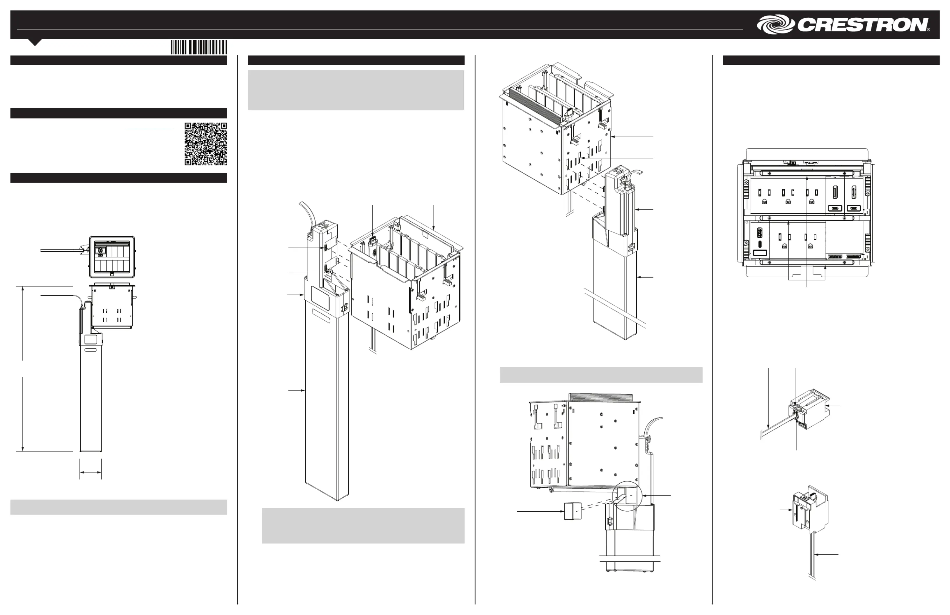
Installing the FT2A-CBLR-GR Retractor into the FT2 FlipTop Assembly (Front View)
Module Installation
Use the following procedure to install the FT2A-CBLR-GR module into an FT2 FlipTop
assembly. If the FT2A-CBLR-GR module is being installed as part of a new FT2 FlipTop
installation, skip ahead to step 3.
1. Remove the magnetic bezel from the FT2 FlipTop assembly by grasping the inside
of the bezel and by rmly pulling it up and away from the assembly until the
magnetic hold is broken.
2. Unscrew and remove the two locking bars on either side of the module row needed
for installation. For example, if installing the FT2-CBLR-GR module in the bottom
row of an FT2-700-MECH or FT2-700-ELEC FlipTop, remove the middle and
bottom locking bars.
Removing the Locking Bars
Keyed
tabs (4)
Locking
tab
Retractor
(extrusion)
Cable connector
(tuck under
assembly)
FT2 FlipTop assembly
NOTE: Once the FT2A-CBLR-GR retractor is secured into the FT2 FlipTop
assembly, a locking tab prevents the retractor from being easily removed. To
remove the retractor after it has been installed, press on the locking tab while
pulling the retractor up and out of the slots in the assembly. Refer to the
illustration above for the position of the locking tab on the retractor neck.
Installing the FT2A-CBLR-GR Retractor into the FT2 FlipTop Assembly (Rear View)
FT2 FlipTop
assembly
Keyed
slots (4)
Locking bars (3)
3. Push down on the two door removal tabs on the bottom of the FT2A-CBLR-GR
module to open the module door.
4. Route the cable connector through the bottom of the module, and then thread the
cable sideways through the slot in the module door so that the connector exits the
inside of the door.
5. Snap the door back into place against the module until is secured.
Installing the Cable into the FT2A-CBLR-GR Module (Bottom View)
Cable
(from retractor)
Insert cable
through slot in
module door
FT2A-CBLR-GR
module
(bottom view)
Door removal
tab (2)
Retractor
(extrusion)
Retractor
(neck)
Retractor
(neck)
Description
The Crestron
®
FT2A-CBLR-GR series provides an assortment of gravity-retractable
cables for use with the FT2-ELEC and FT2-MECH series of FlipTop™ devices. The
included cable retracts into its retractor enclosure only when the cable is held vertically
over its module and released, regardless of how much of the cable has been pulled out
from the retractor. The cable does not retract if it is positioned horizontally on the table.
Overview
Each product in the FT2A-CBLR-GR series provides one retractor that contains an
8' (2.44 m) preinstalled cable and one module that enables the cable connector to be
accessed from the FT2 FlipTop assembly. The retractor is composed of two parts (a
plastic neck and a metal extrusion), and it attaches to the side of the assembly
underneath the table. FT2A-CBLR-GR modules also feature a backlit LED icon that lights
when the module is connected to the power bus in an FT2-ELEC series FlipTop. Refer to
the following illustration for product dimensions.
Additional Resources
Visit the product page on the Crestron website ( ) www.crestron.com
for additional information and the latest rmware updates. Use a QR
reader application on your mobile device to scan the QR image.
3.71 in
(94 mm)
28.38 in
(721 mm)
FT2A-CBLR-GR
module
(top view)
Installing the Cable into the FT2A-CBLR-GR Module (Top View)
Cable
(from retractor)
4. Slide the included metal clip onto the retractor neck as shown in the following
illustration. The clip ts securely between the retractor neck and the bottom side of
the FT2 FlipTop assembly once installed.
NOTE: Pull the cable back and away from the retractor so that the clip slides
onto the retractor neck without becoming impeded by the cable.
Installing the Metal Clip onto the Retractor Neck
Metal
clip
Metal clip
in installed
position
Probleemoplossing Crestron FT2A-CBLR-GR-USB
Als je de handleiding al zorgvuldig hebt gelezen maar geen oplossing voor je probleem hebt gevonden, vraag dan andere gebruikers om hulp
Specificaties
| Merk: | Crestron |
| Categorie: | Niet gecategoriseerd |
| Model: | FT2A-CBLR-GR-USB |