Emko
Temperatuurregelaar
ECO PID+
Emko ECO PID+ Handleiding
Hier is de Emko ECO PID+ (Temperatuurregelaar) gebruikershandleiding. 4 pagina's in taal Engels met een gewicht van 1.2 Mb. Als u geen antwoorden op uw probleem kunt vinden Vraag het onze community.
Pagina 1/4
3
2
1
45
6
Eco PID+, PID Temperature Control Un t�
- 4 d g t process (PV) and 4 d g t set (SV) d splay� � � � �
- Temperature sensor �nput (TC,RTD)
- Programmable ON/OFF, P, PI, PD and PID control forms
- Adaptat on of PID Coeff c ents to the system w th Self-Tune and Auto-Tune � � � �
- Programmable Heat ng or Cool ng Funct ons for Control Output � � �
- Selectable Alarm Funct ons for Alarm Output�
- Ser al RS485 Commun cat on (opt onal)� � � �
Introduct�on Brochure. ENG EcoPID+ 01 V00 03/22
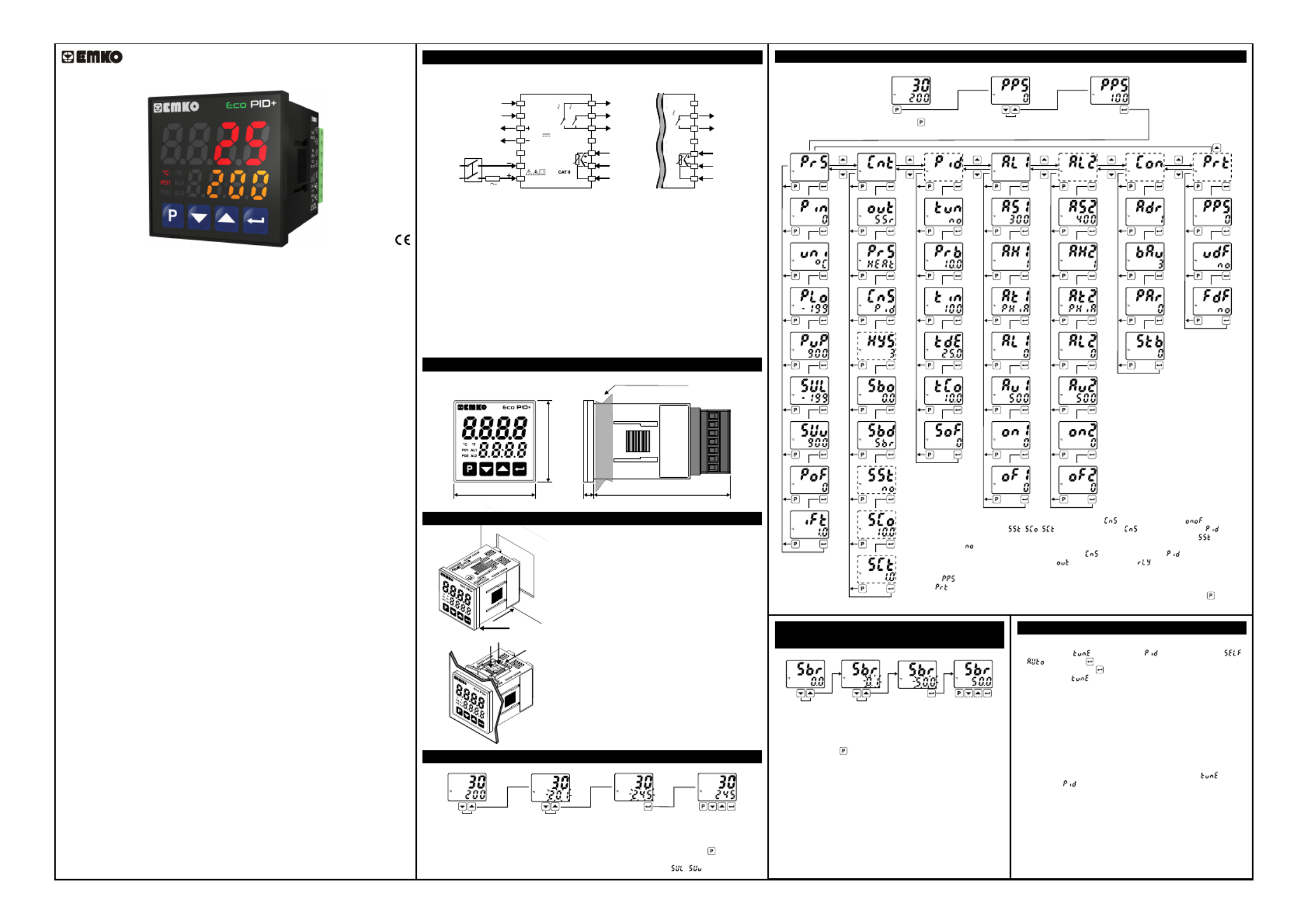
Easy Access D agram For Program Parameters�
Panel Mount ng�
Enter Password w th ncrement� �
or decrement buttons.
Approve password
w th Enter button�
Password Screen
Eco ser es temperature controllers are des gned for measur ng and controll ng a � � � �
temperature value. They can be used n many appl cat ons w th the r TC and RTD � � � � �
temperature measurement nput, mult -funct on control outputs, selectable alarm � � �
funct ons.�
They are ma nly used � �n glass, plast c, petro-chem stry, text le, automot ve and mach ne � � � � �
product on � � �ndustr es. Accurate and advanced controll ng � �s performed w th selectable �
ON-OFF, P, PI, PD, PID and Self Tune/Auto Tune PID funct ons.�
SPECIFICATIONS
Process Input: Thermocouple (TC): J, K, R, S, T and L (IEC584.1)(ITS90)
Thermores stance (RTD): Cu-50 and PT-100 (IEC751)(ITS90)�
Measurement Range: Please refer to process �nput type select on � �n process menu
parameters sect on.�
Accuracy:
Thermocouple (TC):( ± 0.25% of full scale or ± 3ºC, wh ch one � �s greater) ±1 d g t max. � �
Thermores stance (RTD):( ± 0.25% of full scale or ± 2ºC, wh ch one � � �s greater) ±1 d g t � �
max.
Cold Junct on Compensat on:� � Automat cally ±0.1°C/1°C�
L ne Compensat on:� � Max mum 10 Ohm�
Sensor Break Protect on:� Upscale
Sampl ng Cycle: �0.1 second
Input F lter:� Programmable
Control Form: ON/OFF, P, PI, PD or PID (Control form can be programmed by the user)
OUTPUT
Process Output: Relay (5A@250V at res st ve load) or SSR Dr ver Output V� � �
(Max mum 10mA, Max. 12V )�Z
Alarm Output: Relay (5A@250V at res st ve load)V� �
SUPPLY VOLTAGE (It must be determ ned � �n order)
230V (±15%) 50/60Hz - 4VAV
115V (±15%) 50/60Hz - 4VAV
100-240V 50/60Hz - 4VAV
24V (±%15) 50/60Hz - 4VAV
24V (±%15) 50/60Hz - 4VAW
10...30V - 4W Z
DISPLAY
Process D splay:� 16 mm Red 4 d g t LED D splay� � �
Set Value D splay:� 9 mm Orange 4 d g t LED D splay� � �
Led Ind cators:� PO1 (SSR Process Output Status Led), PO2 (Relay
Process Output Status Led), AL1, AL2 (Alarm Output Status Leds),
ºC, ºF LEDs
ENVIRONMENTAL RATINGS and PHYSICAL SPECIFICATIONS
Operat ng Temperature:� 0...50ºC
Hum d ty :� � 0-90%RH (none condens ng)�
Mechan cal Impacts: �1Joule (IK06)
Protect on Class: �NEMA 4X (IP65 at front, IP20 at rear)
We ght:� 150 gr.
D mens on:� � 48 x 48 mm, Depth: 86,5 mm
Panel CutOut: 46 x 46 mm
*1 - ON/OFF Hysteres s parameter s not act ve unless parameter s set as .� � � �
*2 - Soft Start parameters( , , ) s not act ve unless parameter s set as .� � �
*3 - Soft Start Control Output and Soft Start Control T me parameters s not act ve f parameter� � � �
s set as .�
*4 - PID control parameters are not act ve unless parameter s set as .� �
*5 - Alarm-2 parameters are not act ve f parameter s set as .� � �
*6 - Commun cat on parameters are not act ve on dev ces have no commun cat on module.� � � � � �
*7 - If s d fferent from 0 and user enters to program menu w thout enter ng the password� � � �
Prot menu s not shown.�
Note: User can ex t from any parameter screen w thout sav ng the values by press ng button. If � � � �
no operat on for 120 seconds, dev ce automat cally return to ma n screen. � � � �
Easy Access D agram For Sensor Break Output�
Value From Ma n Screen�
Change the sensor break
output value w th ncrement� �
or decrement buttons.
Press Enter button to save
new sensor break output value
and ex t.�
Ma n Screen Ma n Screen� �
Note1: User can ex t from parameter screen w thout sav ng the � � �
values by press ng button. If no operat on for 120 seconds, dev ce � � �
automat cally ex ts from parameter screen.� �
Note2: Sensor break output value can be adjusted on programm ng �
sect on too.�
Tune Operat on�
Start ng the Tune operat on� �
1- Enter to the parameter n menu and select �
or ,then press button for sav ng parameter and turn to ma n � �
screen. Or eas ly press button for 3 seconds* n ma n screen.� � �
2- Observe that bl nks n set d splay.� � �
*Only Self Tune can be started by th s way.�
Cancel ng Tune operat on:� �
1- If sensor breaks;
2- If tune operat on can not be completed n 8 hours;� �
3- Wh le heat ng self tune s runn ng, f process value becomes � � � � �
greater than process set value;
4- Wh le cool ng self tune s runn ng, f process value becomes less � � � � �
than process set value;
5- Wh le tune operat on s runn ng, f user changes the process set � � � � �
value;
6- Wh le tune operat on s runn ng, f user changes the � � � � �
parameter n menu; �
Then tune operat on s canceled, dev ce cont nues to run w th former � � � � �
PID parameters w thout chang ng PID parameters.� �
PID TEMPERATURE CONTROL UNIT
PID+
Eco
D mens ons� �
48 mm / 1.89 nch�
48 mm / 1.89 nch�
6 mm / 0.24 nch�80,52 mm / 3.17 nch�
Max mum 9 mm / 0.35 nch� �
1- Before mount ng the dev ce n your panel, � � �
make sure that the cutout s of the r ght s ze.� � �
2- Check front panel gasket pos t on.� �
3- Insert the dev ce through the cutout. If the �
mount ng clamps are on the un t, put out them � �
before nsert ng the un t to the panel.� � �
4- Insert the mount ng clamps to the two of �
des gnated holes that located four s des of � �
dev ce. �
5- Drag the mount ng clamps n d rect on 5 � � � �
unt l the dev ce completely mmob le w th n the � � � � � �
panel.
6- In order to remove dev ce push on the �
mount ng clamp as shown w th arrow 6 and � �
pull back.
Access and Change Set Values
Press ncrement or decrement�
button to change process set value.
Press Enter button to save new
set value and return the ma n screen.�
Ma n ScreenMa n Screen ��
Temperature Set Value Parameter (Default: 200) MODBUS ADDRESS: 40000
a
Note-1: User can ex t from set value sect on w thout sav ng the values by press ng button. If no � � � � �
operat on for 120 seconds, dev ce automat cally ex ts from Set Value sect on.� � � � �
Note-2: Set value can be adjusted between Set Value Low and H gh L m t ( - ).� � �
Press Program button
to access password screen.
Electr cal W r ngs� � �
To reduce the effect of electr cal no se on dev ce, low voltage l ne (espec ally sensor� � � � �
� � � � � �nput cable) w r ng must be separetely from h gh current and voltage l ne. If poss ble,
use sh elded cable and sh eld must be connected to ground only one s de.� � �
c
Note-1: External Fuse s recommended.�
Note-2: Stranded cable cross sect on: 1,5mm², Sol d cable cross-sect on: 2,5mm²� � �
The str pp ng length s 7mm to 9mm.� � �
Note-3: Supply cables must comply w th the requ rements of IEC 60277 or IEC 60245.� �
It s adv sed to use a two-pole supply sw tch, des gnated for th s dev ce, w th open/� � � � � � �
closed pos t ons marked, n order to cut the power. It must be placed on the supply � � �
� � �nput of the dev ce at a place where the user can eas ly reach.
V External fuse must be on phase connect on of the supply nput.� �
Z External fuse must be on (+) l ne connect on of the supply nput.� � �
Make sure that the power supply voltage range s su table for the dev ce.� � �
Sw tch on the power supply only after all the electr cal connect ons are n place.� � � �
1
2
3
4
5
6
7
8
9
10
11
12
13
14
PO1
(Process Output 1)
SSR Output
12V
Max. 10mA
C
NO
NO
AL1
(Alarm Output 1)
AL2 / PO2
(Alarm Output 2 or
Process Output 2)
Process
Input
5A@250V
5A@250V
Ser al Commun cat on� � �
(RS485, Modbus RTU) A+
B-
PID+
Eco
PT-100
TC
Supply
Sw tch�
L
N
Supply
Voltage
1A T
Fuse
NOTE-1
AL1 / PO2
(Alarm Output 1 or
Process Output 2)
Process
Input
8
9
10
11
C
NO
5A@250V
12
13
14
PT-100
TC
The Dev ce �
w th Two Relays�
The Dev ce �
w th One Relay�
Çal ma Ekranış ı
*1
*5
*2
*4
*2,3
*2,3
*7*6
Probleemoplossing Emko ECO PID+
Als je de handleiding al zorgvuldig hebt gelezen maar geen oplossing voor je probleem hebt gevonden, vraag dan andere gebruikers om hulp
Specificaties
| Merk: | Emko |
| Categorie: | Temperatuurregelaar |
| Model: | ECO PID+ |