Futaba GY470 Handleiding
Hier is de Futaba GY470 (Radiografisch bestuurbaar speelgoed) gebruikershandleiding. 2 pagina's in taal Engels met een gewicht van 991,521.0 Mb. Als u geen antwoorden op uw probleem kunt vinden Vraag het onze community.
Pagina 1/2
F
F
F
Fea
ea
ea
eatures of
tures of
tures of
tures of GY470
GY470
GY470
GY470Features of GY470
Set Contents
Set Contents
Set Contents
Set ContentsSet Contents
The following items are supplied with the GY470:
Functions
Functions
Functions
FunctionsFunctions
Mini screwdriver
Sensor tape
Extension Cord: (Black)
Extension Cord: (Red)
Wiring strap
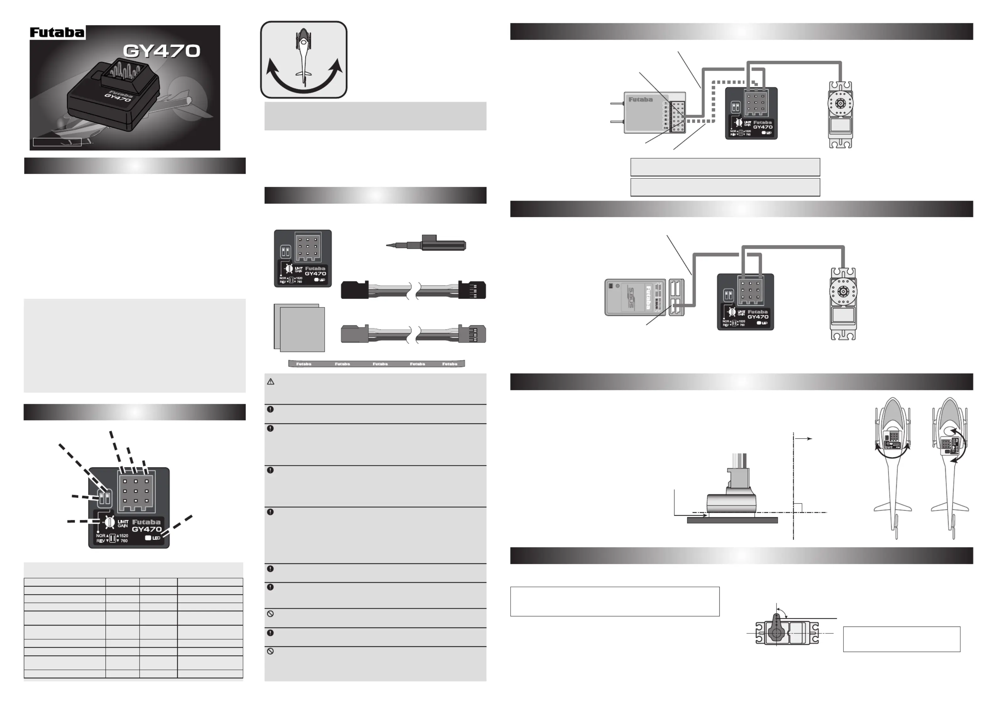
GY470
Monitor LED display
State Color Move Reference
1. GY470 Power ON Orange 2 blinks
2. No servo pulse / Error Red Slow blink
3. Signal input from receiver Green Fast blink
4. Sensor initialization Red/Green ON
AVCS (Red)
Normal (Green)
5. Turn Red/Green Fast blink
Right (Green)
Left (Red)
6. Neutral offset
Orange Slow blink Stick operation
7. Gain off
OFF
8. Switch operation Green One blink
Each time of switch
operation
9. Low battery Red One flash Less than 3.8 V
You can adjust gain from the transmitter by using the remote
gain function. Gain can also be adjusted with the trimmer on the
GY470. The mode switching function allows AVCS/NORMAL
gyro mode switching.
Compact size
20.7x20.7x11mm
and light weight
3.7g
realized by high density mounting technology.
The GY470 can be used immediately with minimum setup.
Only one wire connection to the receiver can operate the GY470.
I MNSTRUCTION ANUAL
I MNSTRUCTION ANUAL
Trimmer
Limit / Gain
LED
Servo Selection Switch
Port1
Rudder input/S.BUS input
Port2
Gain input
Port3
Rudder output
Gyro Direction
Switch
WARNING
Failure to follow these safety precautions may result in severe injury
to yourself and others.
Always check the transmitter and receiver battery voltage to ensure
they have enough remaining capacity to complete the flight.
The GY470 requires 3-5 seconds to initialize when the power is turned
on. Do not move the helicopter and do not move the rudder stick during
this initialization or the gyro may not initialize properly. Once the initializa-
tion process has been completed the rudder servo will move (a little) -sev
eral times indicating that the GY470 is now ready for flight.
Always ensure that there is some slack in the gyro cables to help
maximize performance. Always use the supplied gyro mounting pads to
attach the gyro to the helicopter mechanics. Do not use a strap that en-
compasses the GY470 sensor. This may affect the overall performance of
the gyro.
If you are switching between NORMAL mode and AVCS mode in flight,
please keep in mind that you must have the gyro re-learn the center posi-
tion after making a trim change within the transmitter. To memorize the
new center position simply flip the gain switch on the transmitter three
times between NORMAL mode and AVCS mode (NORMAL
AVCS
N
ORMAL
AVCS
NORMAL
AVCS) within one second. The servo will
center indicating that the new center position has been memorized.
Be sure to use a digital servo. Use only digital servos with the GY470.
Using the GY470 with an analog servo will damage the servo.
Always check the direction of operation of the servos. If you attempt to
fly the model when a servo operates in the wrong direction, the fuselage
will spin in a fixed direction and enter an extremely dangerous state.
Do not drop the GY470 onto a hard surface or subject the GY470 to a
strong shock as this may damage the sensor.
When using the in the AVCS mode, set revolution mixing to GY470
OFF.
Do not place gyro near heating equipment (engine, motor, ESC, bat-
tery, servo, etc.). Always allow the gyro to adjust to the surrounding envi-
ronmental temperature before flight. A large temperature change during
use will cause drift and other operational issues.
Install the sensor so that the bottom of the
gyro is perpendicular to the main rotor shaft
axial direction. Offset of this axis will also re-
act in the roll and pitch directions.
As shown in a gure, the direc-
tion which sticks GY470 is free.
Before using your new gyro, please read this manual thoroughly
and use the gyro properly and safely. After reading this manual,
store it in a safe place.
Thank you for purchasing a GY470
gyro, a rate gyro for RC helicopters.
GY470 is a lightweight micro gyro
developed for RC helicopter rudder
(yaw axis) control. It can be used with
mininum setup and includes an S.BUS/
S.BUS2 port.
(Integrated sensor type rate gyro)
• Gyro sensor: MEMS vibrating structure gyro
• Operating voltage: DC4.0 V to 8.4 V
• Current drain: 30
mA (excluding a servo)
• Operating temperature range: -10 ºC to +45 ºC
• Dimensions: 20.7 x 20.7 x 11.0 mm (except protrusion)
• Weight: 3.7 g
• Functions: Sensitivity trimmer. LED monitor. Servo selection (1520 uS,
760 uS). S.BUS/S.BUS2 connection.
*Oil on the sensor bottom and the part in-
stalled to the frame can be wiped off with
cleaner, etc.
GY470 installation precautions
·In the rudder neutral position, connect the linkage at the position at
which the servo horn and control wire are perpendicular.
Perpendicular
Control wire
Set the servo horn length based on
the helicopter manufacturer's instruc-
tions.
Probleemoplossing Futaba GY470
Als je de handleiding al zorgvuldig hebt gelezen maar geen oplossing voor je probleem hebt gevonden, vraag dan andere gebruikers om hulp
Specificaties
| Merk: | Futaba |
| Categorie: | Radiografisch bestuurbaar speelgoed |
| Model: | GY470 |