Microchip
Niet gecategoriseerd
MD1711
Microchip MD1711 Handleiding
Hier is de Microchip MD1711 (Niet gecategoriseerd) gebruikershandleiding. 20 pagina's in taal Engels met een gewicht van 2.5 Mb. Als u geen antwoorden op uw probleem kunt vinden Vraag het onze community.
Pagina 1/20
2019 Microchip Technology Inc. DS20005740A-page 1
MD1711
Features
• Drives Two Ultrasound Transducer Channels
• Generates a Five-Level Waveform
• Drives 12 High-Voltage MOSFETs
• ±2A Source-and-Sink Peak Currents
• Up to 20 MHz Output Frequency
• 12 V/ns Slew Rate
• ±3 ns Matched Delay Times
• Less than –40 dB Second Harmonic
• Two Separate Gate Drive Voltages
• 1.8V to 3.3V CMOS Logic Interface
Applications
• Medical Ultrasound Imaging
• Piezoelectric Transducer Drivers
• Non-Destructive Testing (NDT)
• Metal Flaw Detection
• Sonar Transmitter
General Description
The MD1711 is a two-channel logic controller circuit
with low-impedance MOSFET gate drivers. It is
intended to be used with external FETs as a five-level
high-voltage and high-speed transmitter. The MD1711
is designed for medical ultrasound imaging
applications but can also be used for metal flaw
detection, NDT and for driving piezoelectric
transducers.
The MD1711 has two sets of control logic inputs, one
for Channel A and one for Channel B. Each channel
consists of three pairs of MOSFET gate drivers. These
drivers are designed to match the drive requirements of
the TC6320. One MD1711 drives six TC6320s. Each
driver consists of an N-channel and a P-channel
MOSFET. They are designed to have the same
impedance and can provide peak currents of 2 amps.
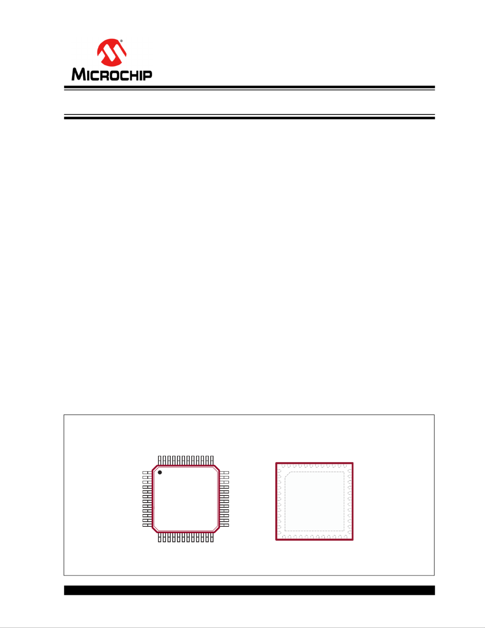
Package Types
48-lead LQFP
(Top view)
See Table 2-1 for pin information.
48-lead QFN
(Top view)
1
48
1
48
High-Speed Integrated Ultrasound Driver IC
Probleemoplossing Microchip MD1711
Als je de handleiding al zorgvuldig hebt gelezen maar geen oplossing voor je probleem hebt gevonden, vraag dan andere gebruikers om hulp
Specificaties
| Merk: | Microchip |
| Categorie: | Niet gecategoriseerd |
| Model: | MD1711 |