Crestron
Schakelaar
CLW-SWEX-P
Crestron CLW-SWEX-P Handleiding
Hier is de Crestron CLW-SWEX-P (Schakelaar) gebruikershandleiding. 2 pagina's in taal Engels met een gewicht van 591,808.0 Mb. Als u geen antwoorden op uw probleem kunt vinden Vraag het onze community.
Pagina 1/2
CLW-SWEX-P
Cameo
®
Wireless In-Wall Switch, 120 V
Operations & Installation Guide
Description
Crestron
®
in-wall dimmers and switches are modeled after the popular, modern look of
Cameo
®
keypads. Available with adjustable button layouts and designer colors, the
Cameo dimmers and switches are more versatile and affordable than previous
generations. Like their cousin keypads, button caps can be swapped in the eld, making it
easy to change engraving or color. And their streamlined look inspires the combination of
in-wall lighting control with centralized lighting control—delivering the ultimate, entire
home control solution.
Specications
Specications for the CLW-SWEX-P are listed in the following table.
CLW-SWEX-P Specications
Installation
WARNING: To avoid re, shock, or death, turn off power at circuit breaker or fuse and
test that power is off before wiring!
WARNING: New installations should be checked for short circuits prior to installing a
CLW-SWEX-P switch. With the power off, close the circuit and restore power. If the loads
do not work or a breaker trips, check and correct the wiring or xture (if necessary). Install
the switch only when the short is no longer present. The warranty is void if the switch is
installed and operated with a shorted load.
NOTES: Observe the following points.
• This product should be installed and used in accordance with appropriate electrical
codes and regulations.
• This product should be installed by a qualied electrician.
NOTE: Before using the CLW-SWEX-P, ensure the device is using the latest rmware.
Check for the latest rmware for the CLW-SWEX-P at www.crestron.com/rmware.
Firmware is loaded onto the device using Crestron Toolbox™.
1. Turn power off at the circuit breaker.
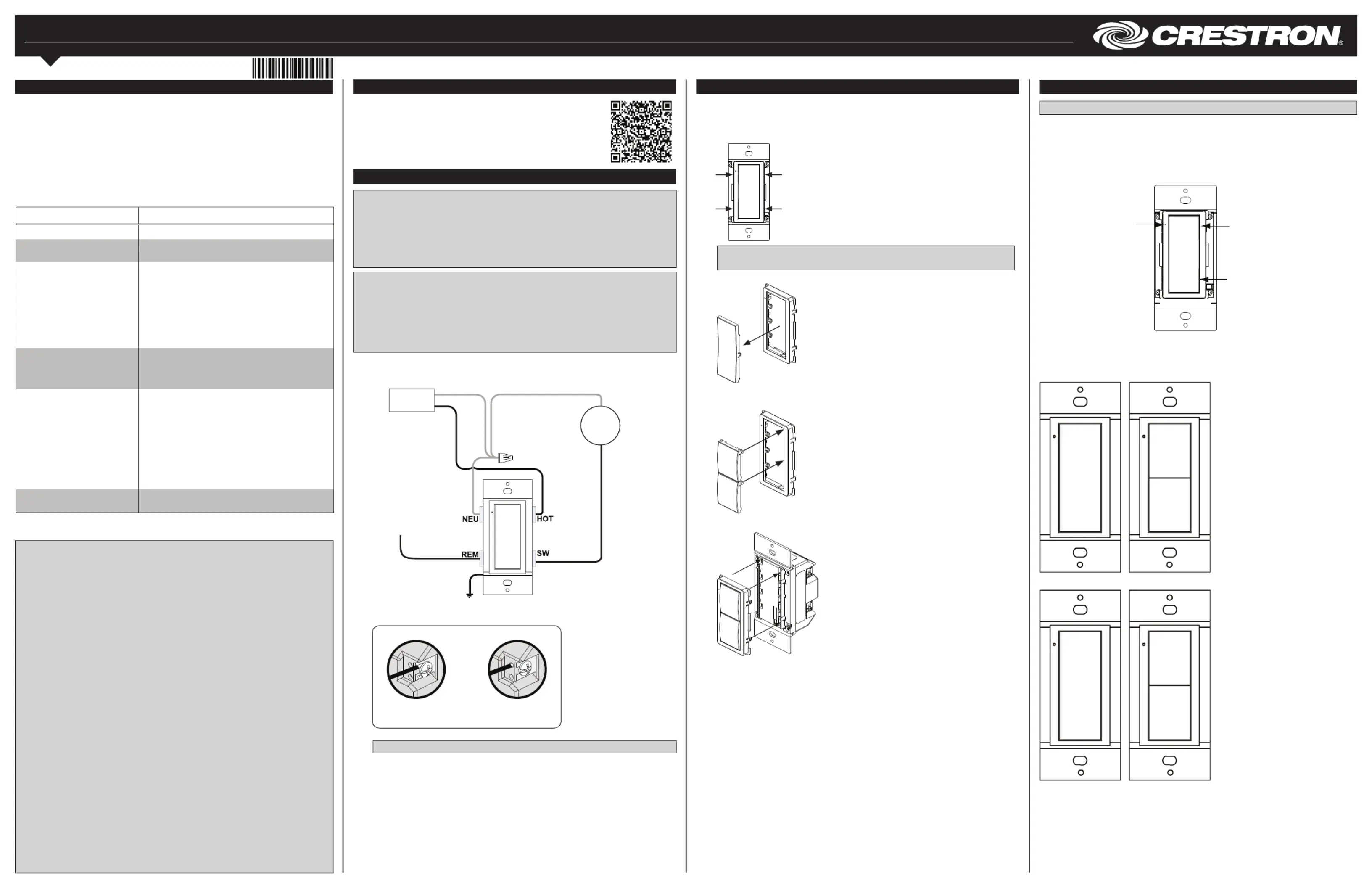
2. Wire the device as shown in the following diagrams.
Wire the CLW-SWEX-P
Additional Resources
Visit the product page on the Crestron website (www.crestron.com) or
scan the QR code to the right for additional information and the latest
rmware updates.
* A neutral wire is required for normal operation.
Important Notes (Read Before Installation)
CAUTION: TO REDUCE THE RISK OF OVERHEATING AND POSSIBLE DAMAGE TO
OTHER EQUIPMENT, DO NOT INSTALL TO CONTROL A RECEPTACLE OR A
TRANSFORMER-SUPPLIED APPLIANCE.
ATTENTION: GRADATEURS COMMANDANT UN BALLAST-AFIN DE RÉDUIRE LE
RISQUE DE SURCHAUFFE ET LA POSSIBILITÉ D’ENDOMMAGEMENT À D’AUTRES
MATÉRIELS, NE PAS INSTALLER POUR COMMANDER UNE PRISE OU UN APPAREIL
ALIMENTÉ PAR UN TRANSFORMATEUR.
• Neutral: The CLW-SWEX-P requires a neutral connection to operate.
• Codes: Install in accordance with all local and national electrical codes.
• Wiring: Use copper wire only that are rated for at least 75°C.
• Lamp Type: For use with permanently installed incandescent, magnetic low voltage,
tungsten-halogen, or CFL only.
• Temperature: For use where temperatures are between 32° to 104°F (0° to 40°C).
• Electrical Boxes: Devices mount in standard electrical boxes. For easy installation,
use 3 1/2 in (89 mm) deep electrical boxes. Several devices can be installed in one
electrical box (multigang). For a smooth appearance, one-piece multigang
faceplates (not supplied) can be installed. When installing into a multigang box, do
not fully tighten the devices to the box until the faceplate has been aligned.
• Switches: Mechanical 3- or 4-way switches do not work with the CLW-SWEX-P
series switchers.
• Spacing: If mounting one device above another, leave at least 4 1/2 in (115 mm)
vertical space between them.
• Low Voltage Applications: Operation of a low voltage circuit with all lamps
inoperative or removed may result in current ow in excess of normal levels. To
avoid transformer overheating and premature transformer failure, Crestron
recommends the following:
> Do not operate low voltage circuits without operative lamps in place.
> Replace burned-out lamps as quickly as possible.
> Use transformers that incorporate thermal protection or fuse transformer
primary windings to prevent transformer failure due to overcurrent.
Make Connections to the CLW-SWEX-P
NOTE: Refer to the CLW-SLVU-P Installation Guide (Doc. 7364) for wiring details.
3. Push all power wires back into the electrical box and fasten the device to the electrical
box with the provided screws.
4. Attach the decorative faceplate.
5. Ensure all buttons actuate without sticking.
6. Restore power at the circuit breaker.
YesNo
Do not insert the wires behind the screw head.
Insert the wires into the wire entry holes.
Changing Button Assemblies
The button assembly can be removed and replaced with other button assemblies. To
change a button assembly, perform the following procedure.
1. Remove the button assembly by squeezing the sides of the bezel near the bezel
snaps, as shown in the following diagram.
Squeeze at the arrow
points and pull to
remove the button
assembly.
NOTE: When the button assembly is removed, power to the unit and load is
removed automatically.
2. Remove the button(s) from the front of the button assembly.
Gently spread the
frame apart to remove
the buttons.
3. Insert the new buttons through the front of the bezel and snap them into place.
Ensure that the LED is on the left side.
4. Attach the button assembly to the device. Ensure that the LED is on the left side.
Gently spread the
frame apart to insert
the buttons.
Operation
NOTE: The device may be warm to the touch during operation. This is normal.
Basic Operation
Operation described in this guide assumes the CLW-SWEX-P is operating in Local mode
(without the use of a control system). The CLW-SWEX-P can also operate in Remote
mode in which button behavior is dictated entirely by the control system program. The
CLW-SWEX-P is shipped with a rocker switch already installed. In this conguration, the
unit will function as shown below.
The LED is bright when the
load is on and dim when
the load is off (night light).
Tap to turn on the
load.
Tap to turn off the
load.
Default Button Functions
The gures below illustrate the default functions available for each physical button
conguration and tap action sequence.
Button Press
Double Button Press (Press Twice within 1/2 Second)
Master and Slave Operation
For more information on master and slave operation, refer to the CLW-SLVU-P Installation
Guide (Doc. 7364).
1. Delayed off can be added via control system programming.
2. Fast off functionality is only performed if a delay has been added via control system programming.
On
On
—
—
Off
1
Fast
Off
2
Off
1
Fast
Off
2
Black
Black
White
Line
120 V~
Load
White
To one or more
CLW-SLVU-P
(Optional, sold
separately)
SPECIFICATION DETAILS
Power Requirements 120 Vac, 60 Hz, line power
Load Types CFL, Electronic Ballasts, Incandescent, Magnetic
Low Voltage, Tungsten-Halogen
Load Ratings
Minimum Load 25 W
Incandescent/Tungsten
Halogen/Magnetic
Ballasts
1000 VA/W
Electronic Ballasts/CFL 600 VA
Motor 1/2 HP
Environmental
Temperature 32° to 104°F (0° to 40°C)
Humidity 10% to 90% RH (non-condensing)
Connections
Hot (1) 14-12 AWG, screw terminal, brass, line power
input
Remote (1) 14-12 AWG, screw terminal, blue, remote
Load (1) 14-12 AWG, screw terminal, red, load output
Neutral (1) 14-12 AWG, screw terminal, silver, neutral*
Ground (1) 18 AWG Class 1 ying lead, green, ground
(wire nut included)
Maximum Number of
Remote CLW-SLVU-P Units
9
Probleemoplossing Crestron CLW-SWEX-P
Als je de handleiding al zorgvuldig hebt gelezen maar geen oplossing voor je probleem hebt gevonden, vraag dan andere gebruikers om hulp
Specificaties
| Merk: | Crestron |
| Categorie: | Schakelaar |
| Model: | CLW-SWEX-P |