Microchip
Niet gecategoriseerd
HV9910B
Microchip HV9910B Handleiding
Hier is de Microchip HV9910B (Niet gecategoriseerd) gebruikershandleiding. 12 pagina's in taal Engels met een gewicht van 1.3 Mb. Als u geen antwoorden op uw probleem kunt vinden Vraag het onze community.
Pagina 1/12
Supertex inc.
Supertex inc.
www.supertex.com
Doc.# DSDB-HV9910BDB3
A032813
HV9910BDB3
General Description
The HV9910BDB3 demoboard is a high current LED driver
designed to drive one LED or two LEDs in series at currents
up to 1.0A from a 10 – 30VDC input. The demoboard uses
Supertex’s HV9910B Universal LED driver IC to drive a
buck converter.
The HV9910BDB3 can be congured to operate in either a
constant frequency mode (for driving a single LED) or in a
constant o-time mode (for driving two LEDs).
The output current can be adjusted in two ways – either
with linear dimming using the onboard potentiometer or
with PWM dimming by applying a TTL – compatible square
wave signal at the PWMD terminal. Using linear dimming,
the output current of the HV9910DB1 can be lowered to
about 0.01A (note: zero output current can be obtained
only by PWM dimming).
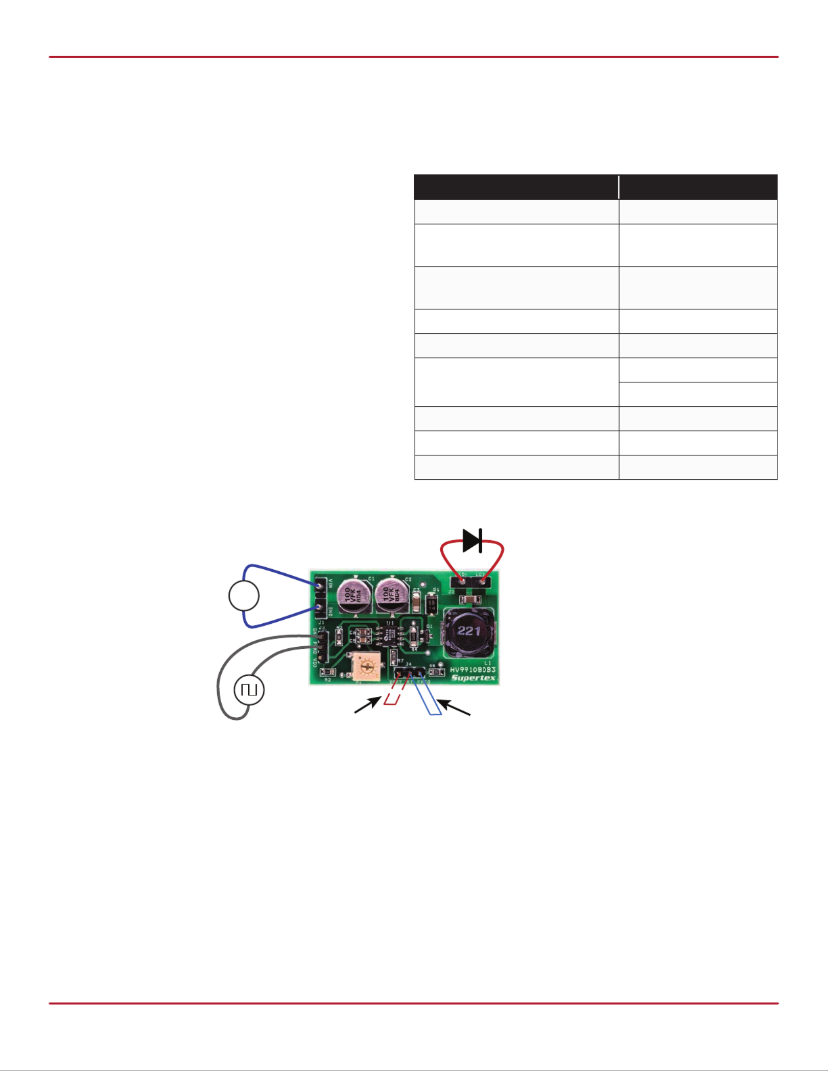
Connection Diagram
Low Voltage, High Current,
LED Driver Demoboard
Specications
Parameter Value
Input voltage 10 - 30VDC
Output voltage -
constant frequency mode 2.0 - 4.5V
Output voltage -
constant o-time mode 4.0 - 8.0V
Maximum output current 1.0A ± 10%
Output current ripple (typ) 20% (peak-peak)
Efciency (@ 12V input) 86% (for one LED)
93% (for two LEDs)
Open LED protection yes
Output short circuit protection no
Dimensions 48.2mm X 29.0mm
Connections
1. Input Connection - Connect the input DC voltage
between VIN and GND terminals of connector J1 as shown
in the connection diagram.
2. Output Connection - Connect the LEDs between
LED+ (anode of LED string) and LED- (cathode of LED
string) of connector J2.
a. If the load is one LED, short the RT and FREQ
terminals of connector J4 using a jumper.
b. If the load is two LEDs, short the RT and OFFT
terminals of connector J4 using a jumper.
3. PWM Dimming Connection
a. If no PWM dimming is required, short PWMD and
VDD terminals of connector J3.
b. If PWM dimming is required, connect the TTL-
compatible PWM sourc between PWMD and GND
terminals of connector J3. The recommended PWM
dimming frequency is ≤ 1.0kHz.
+
Short for constant
frequency mode
+
-
Short for
constant o-time mode
Probleemoplossing Microchip HV9910B
Als je de handleiding al zorgvuldig hebt gelezen maar geen oplossing voor je probleem hebt gevonden, vraag dan andere gebruikers om hulp
Specificaties
| Merk: | Microchip |
| Categorie: | Niet gecategoriseerd |
| Model: | HV9910B |